Here are some photos of the setup I put together for making disk images from Fairlight floppies. It uses a Mitsubishi M2894-63 8 inch floppy drive with a Meanwell RD-50B PSU where I split off 120 VAC and make the +5 and +24V lines that the 8″ drive needs to operate.
Also shown is a custom-made cable I made to adapt the 50 pin edge connector on the 8″ drive to 34 pins used in modern PCs. The cable was based on the information on this excellent website – http://www.classiccmp.org/dunfield/img/index.htm
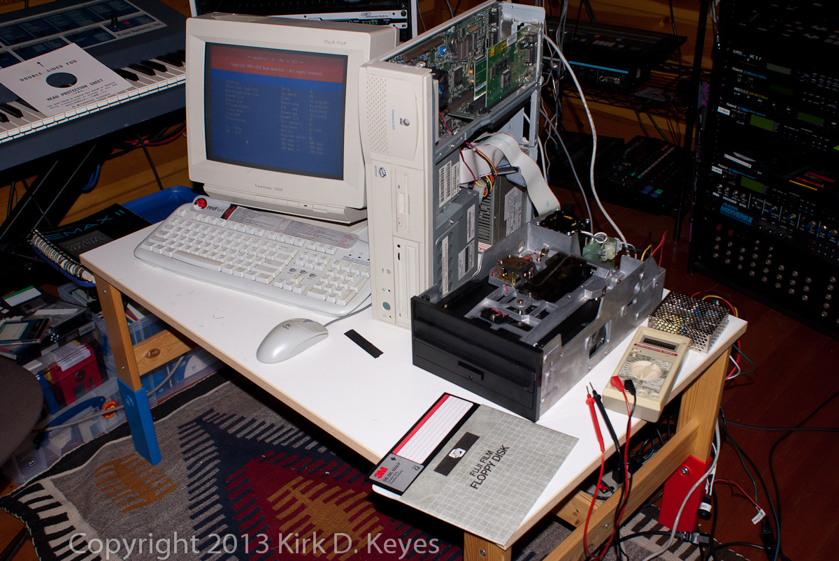 |
Here’s the general layout of the disk imaging setup. |
 |
Close-up of my vintage ca. 1995 AT&T “Globalyst 620” Pentium 100 PC. I bought this PC in about the year 2000 for about $20 to use as a Linux Floppy Firewall box. I also upgraded the OS from Windows 95 to Win98SE. You can see the floppy cable hanging out the top side of the box heading down to the 8-inch floppy drive. |
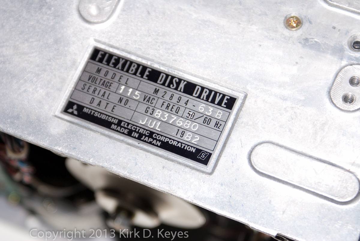 |
The ID plate for the Mitsubishi M2894-63 8 inch floppy drive. This drive is compatible with the Fairlight CMI. Keep in mind it is what is known as a “half-height” drive, and it weighs 7.8 pounds! |
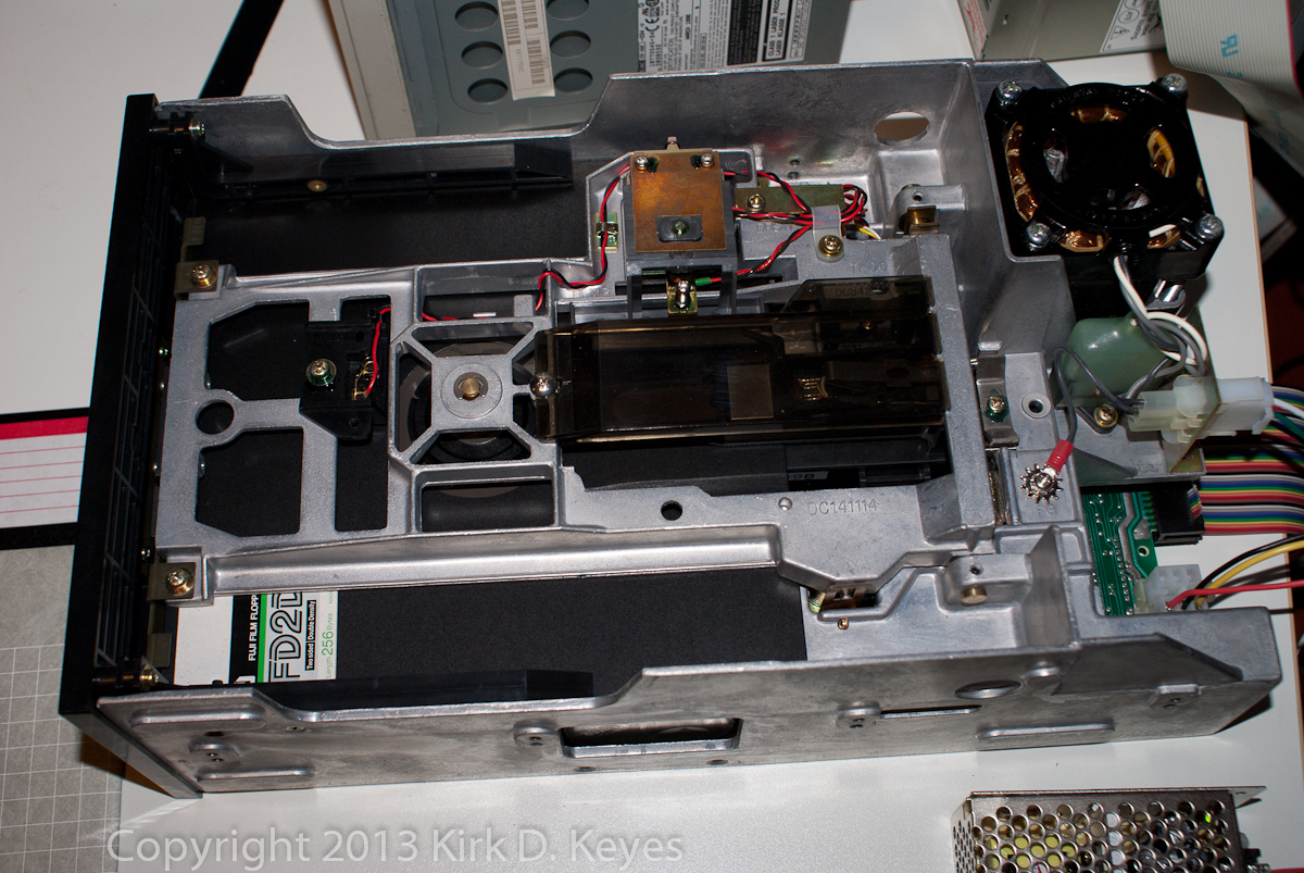 |
Top view of the Mitsubishi M2894-63 8″ drive. You can see the 120 VAC disk drive motor on the back corner. The read/write head is protected by a transparent black plastic cover in the center of this photo. |
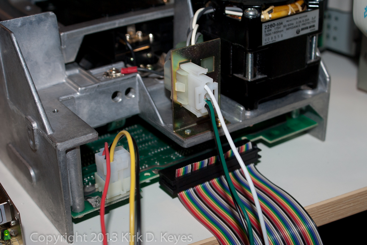 |
The rear connections of the 8″ drive. The 50 pin edge connector has Pin 1 on the far side from the photo, where the rainbow-colored ribbon connector is attached (black wire on the ribbon’s far edge). The 120 VAC input is the 3-wire connector (black, green, and white wires) directly about the 50 pin ribbon cable. The +5V and +24V supply come in with the 6-wire connector to the left of the ribbon cable with the black, red, and yellow wires. |
 |
Here’s the headlock shipping card that came in the Mitsubishi disk drive. |
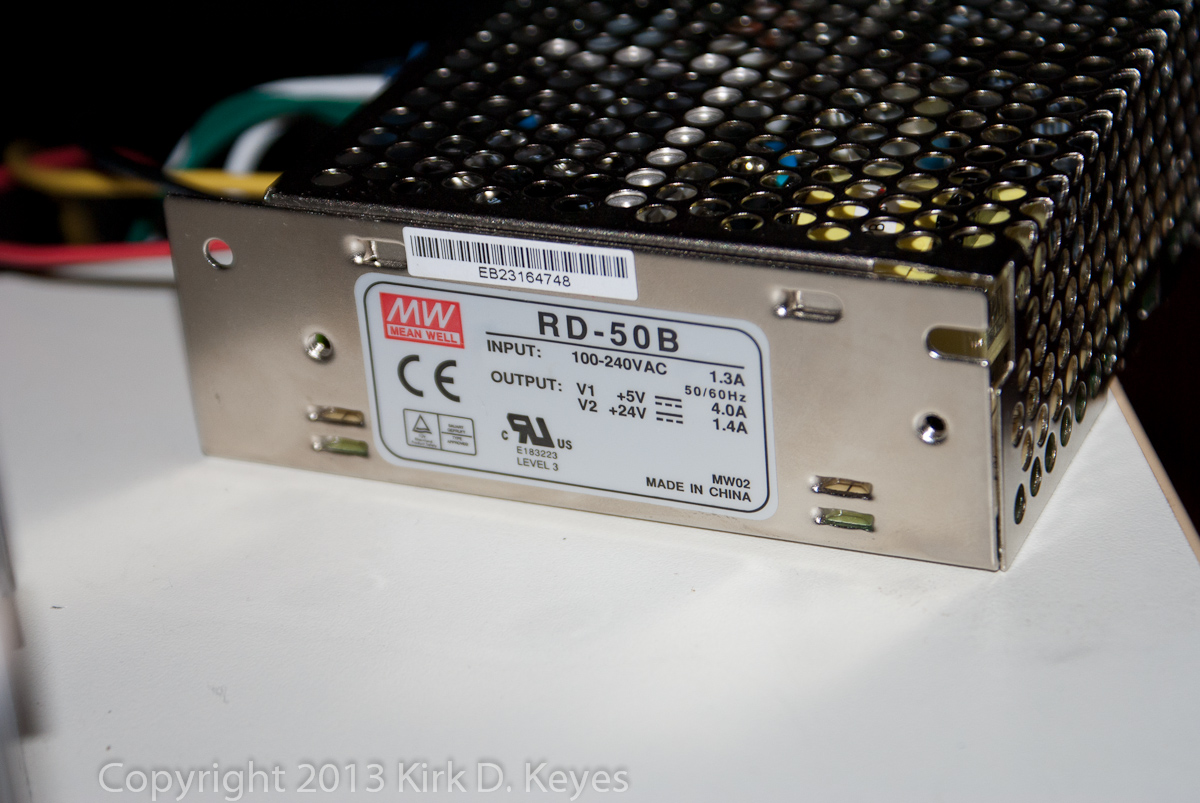 |
The Meanwell RD-50B power supply converts 120 VAC to +5V and +24V needed by the 8″ drive. I used a separate PSU instead of the Fairlight’s PSU in case something catastrophic happened… |
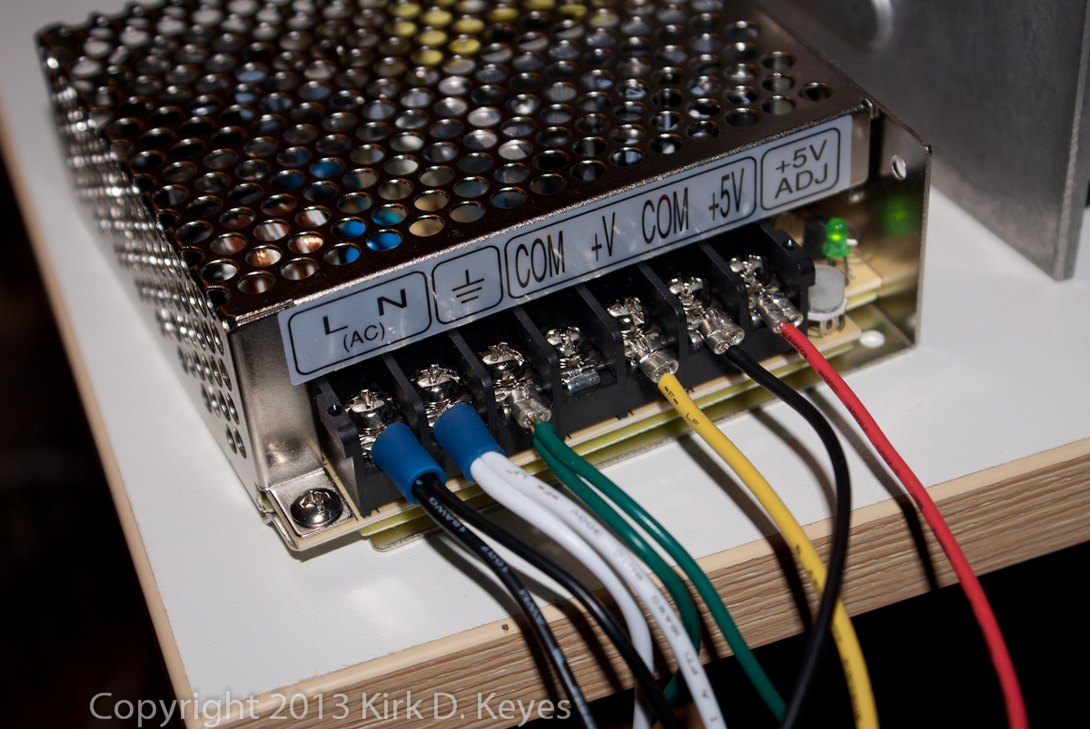 |
Here are the leads connected to the Meanwell PSU. The V+ line produces +24V on this PSU. The two COM connectors are connected internally in the PSU, so I only needed to use one wire for the ground. |
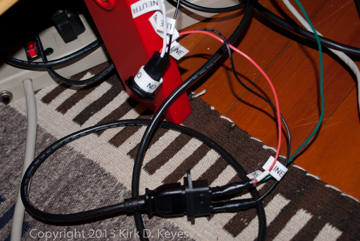 |
Here are my half-assed power cable connection and power switch. Not very safe – I’d recommend mounting them in an enclosure, so no one gets electrocuted! |
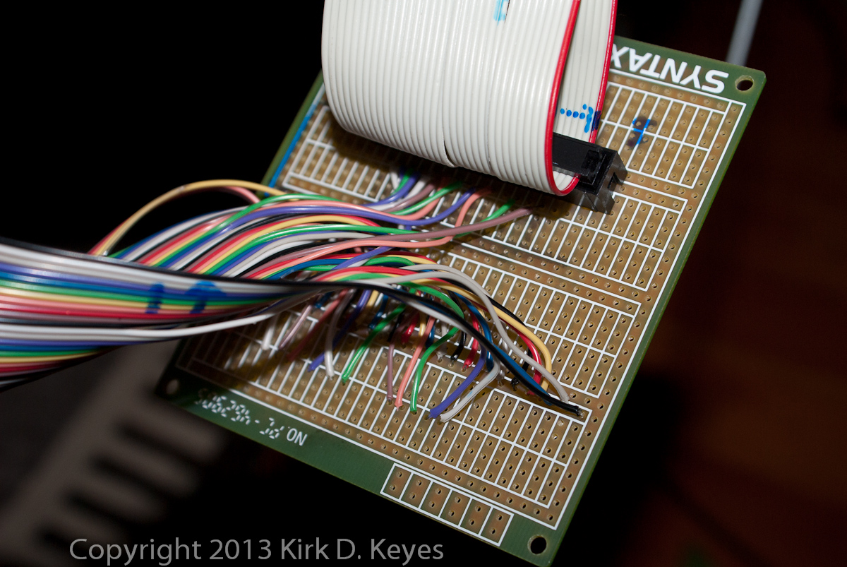 |
Here’s where the magic happens! This board shows the wires from the 50 pin ribbon connected to the appropriate wires in the 34 pin PC floppy drive cable. I used a 34 pin IDC header to connect the floppy drive cable from the PC instead of stripping and soldering each wire from that cable to the board as I did with the 50 wire ribbon. Half the wires on both the 50 and 34 pin ribbon cables are connected to the ground, so I used the traces on the board to make all those connections, so all I needed to do was solder them in at the right places. The unused wires on the 50 pin ribbon cable are solders on the lower side of the board so that they weren’t hanging around, shorting out on anything. |
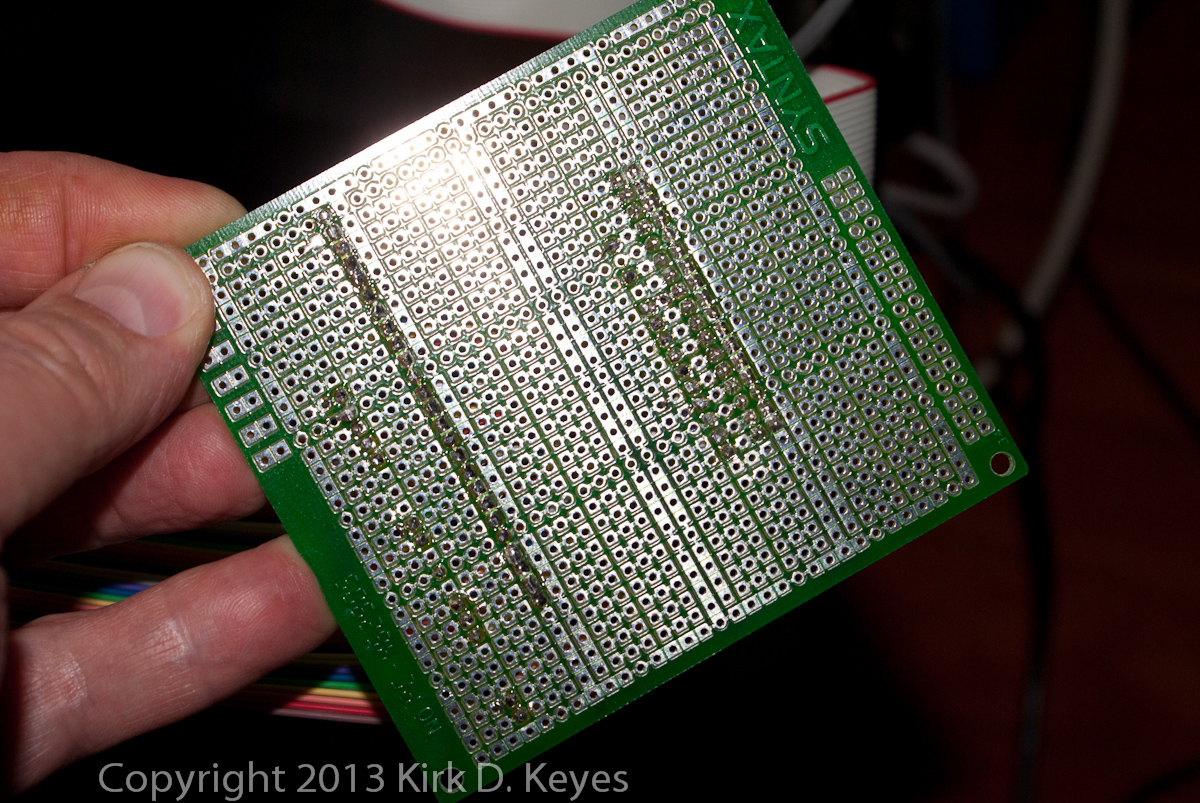 |
Here’s the back is the board showing my rudimentary soldering skills. |
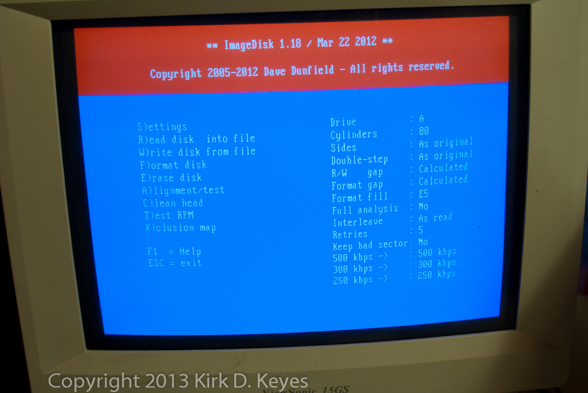 |
ImageDisk V.1.18 software running on the PC. The PC has Windows 98SE installed on it, and it has been restarted in DOS mode. These are the default setting when ImageDisk starts up – note it is set for Drive A and 80 cylinders. |
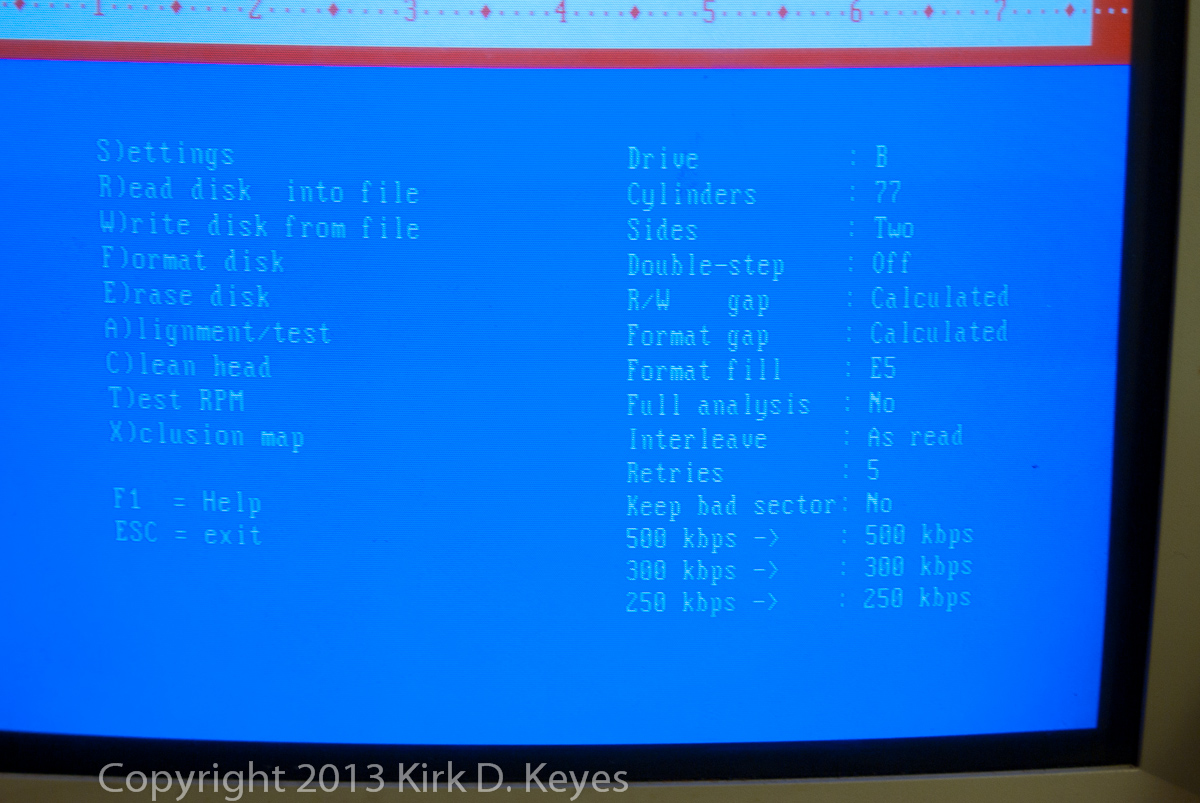 |
These are the settings I used for the Fairlight floppy disks with the cable adaptor that I made – Drive B, 77 cylinders, Two Sides, Double-step Off. |
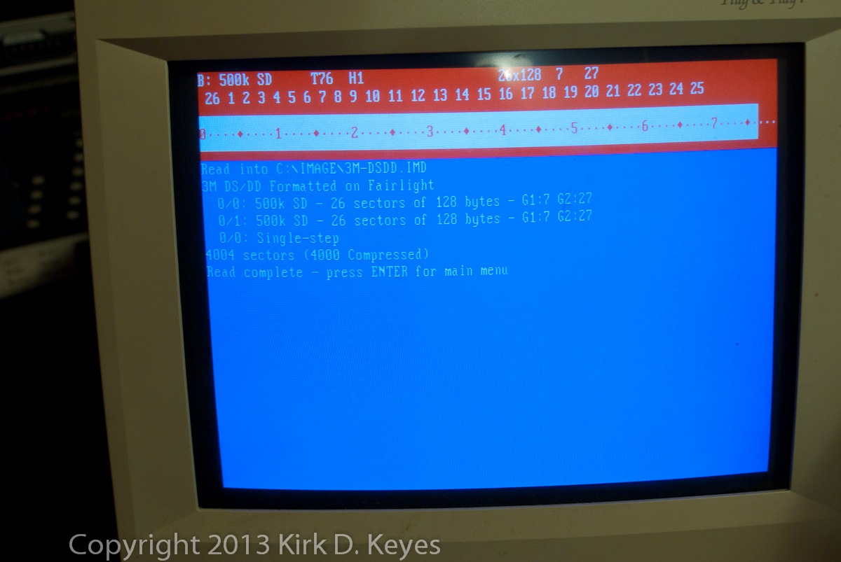 |
Test read of a 3M DS/DD 8 inch floppy previously formatted on the Fairlight using the “CFG O” command in QDOS to format the disk for storing sounds. Note that the disk is formatted as SD, not DD, with 26 sectors of 128 bytes each. |
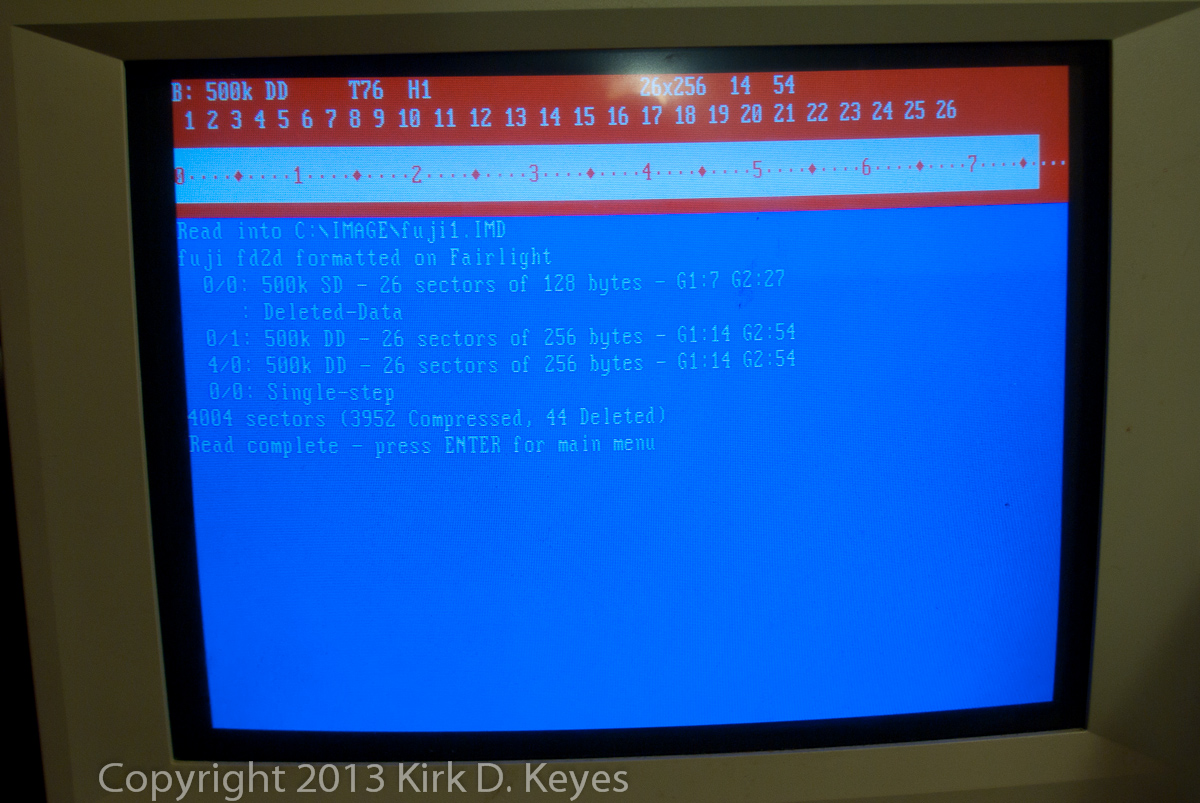 |
A test read of a Fuji FD2D DS/DD 8 inch floppy previously formatted on the Fairlight using the “CFG O” command in QDOS to format the disk for storing sounds. This disk appeared to format correctly on the Fairlight (well, at least there were no errors from the Fairlight during formatting). Note it says the disk is formatted as DD, not SD like with the 3M disk, with 26 sectors of 256 bytes each. This Fuji disk shows no free space after formatting when checked on Page 2. |
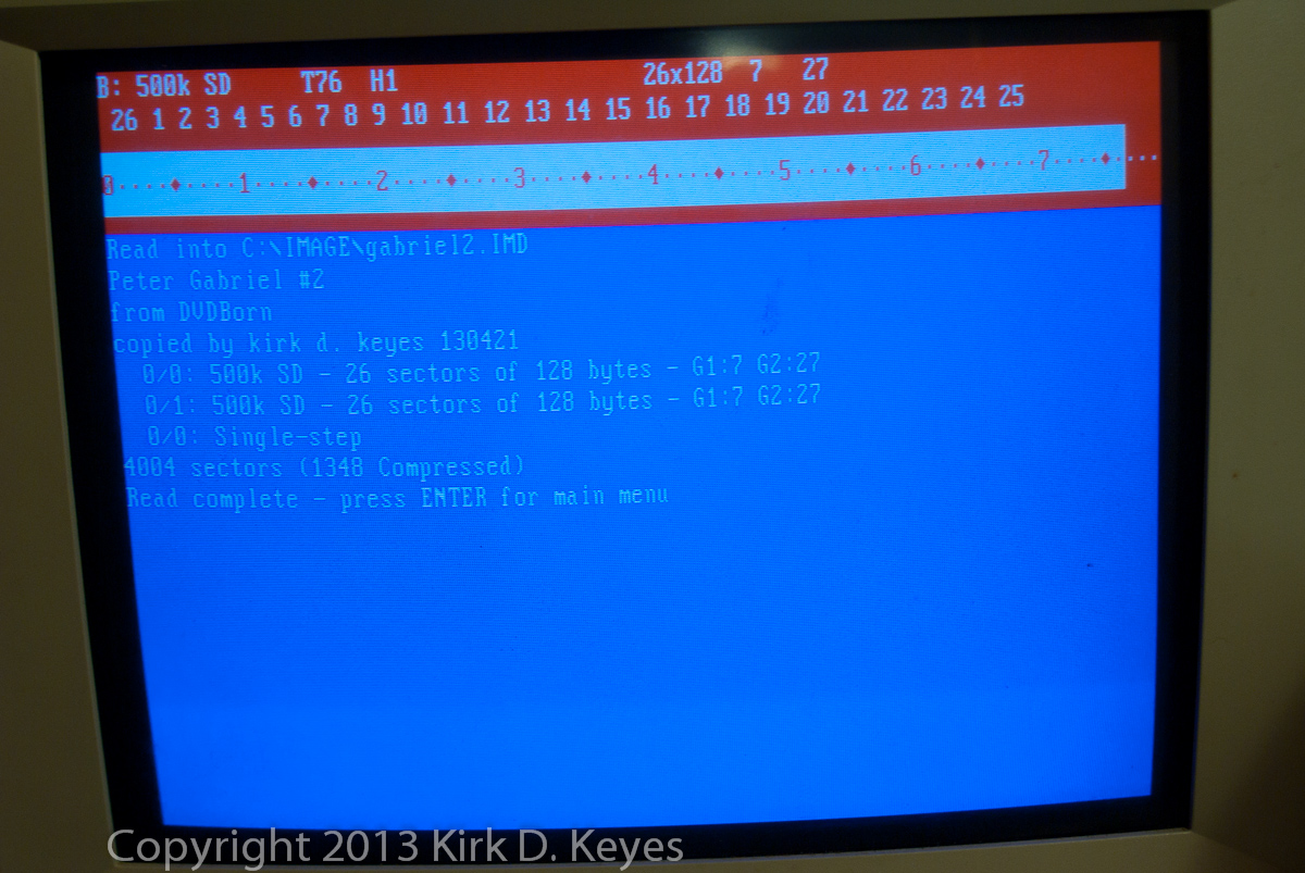 |
Test imaging of a Peter Gabriel disk. Imaging appears to have worked! |
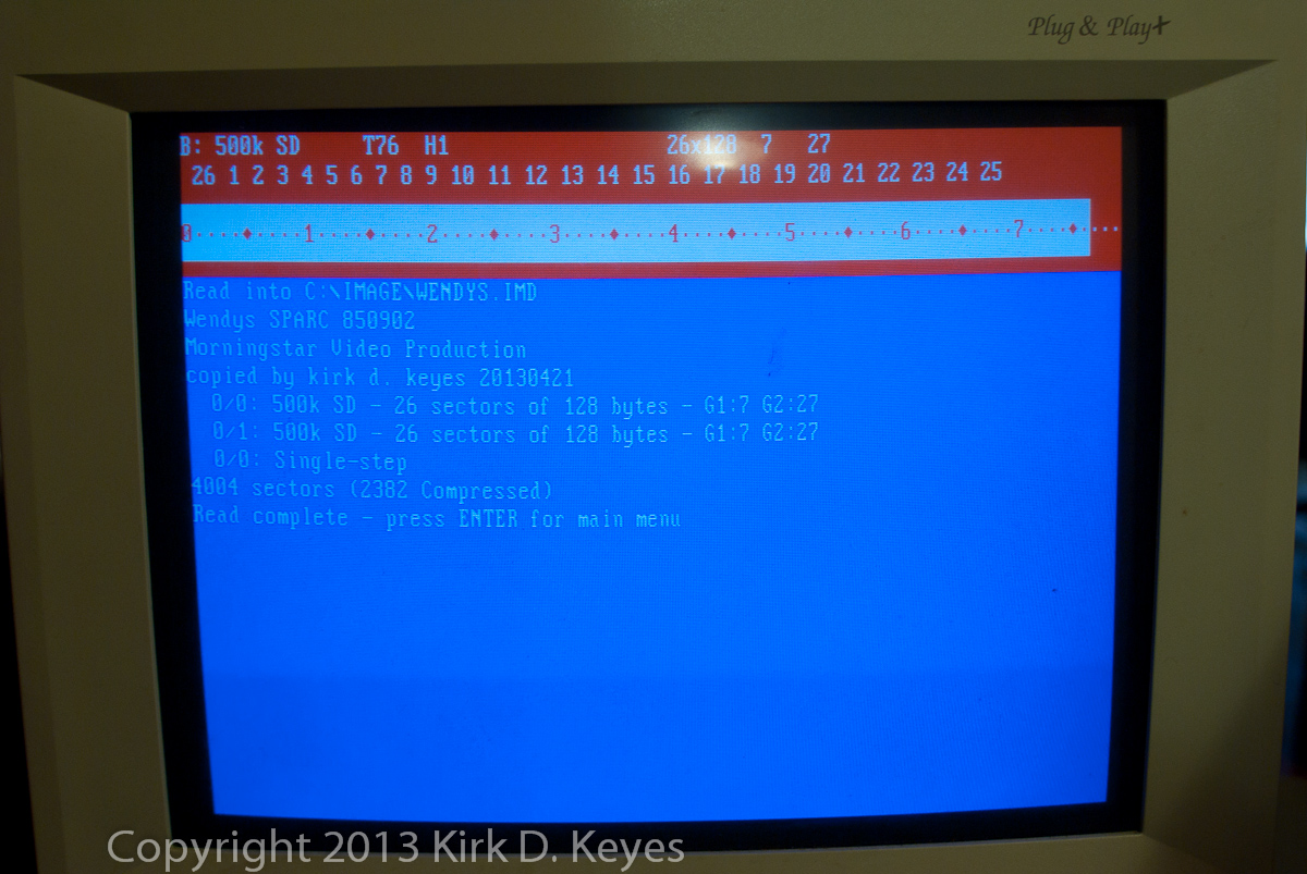 |
Test imaging of a Wendys TV commercial soundtrack disk from 1985. Imaging appears to have worked! |
 |
Imaging underway!! |
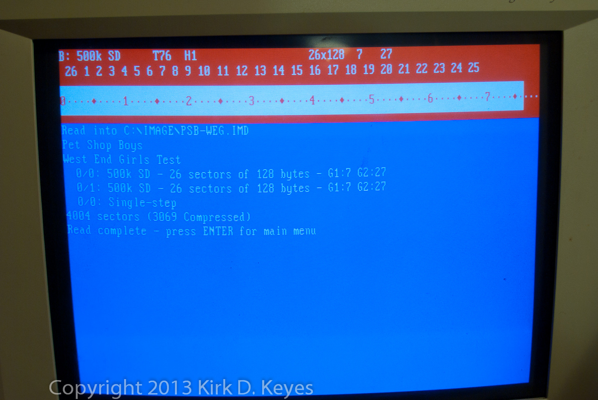 |
Test image of PSB West End Girls disk. Also appears to have worked. |
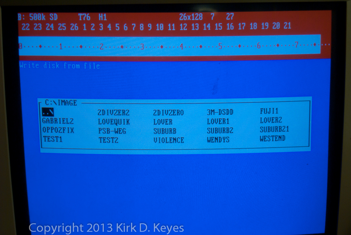 |
Selecting a disk image to write to disk – you give ImageDisk the “W” command to write a disk image to the floppy, and then it shows you a menu of disk images you can select from in the current directory. You cursor over to the image you want to write and then press “Enter.” |
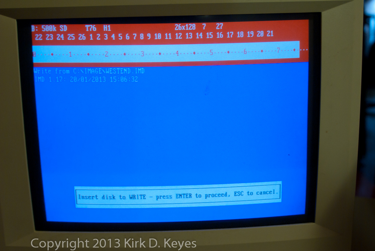 |
The software then tells you to insert a disk into the floppy drive and press “Enter” again, and then it writes the image onto an 8-inch floppy disk!! It’s like magic! |
|
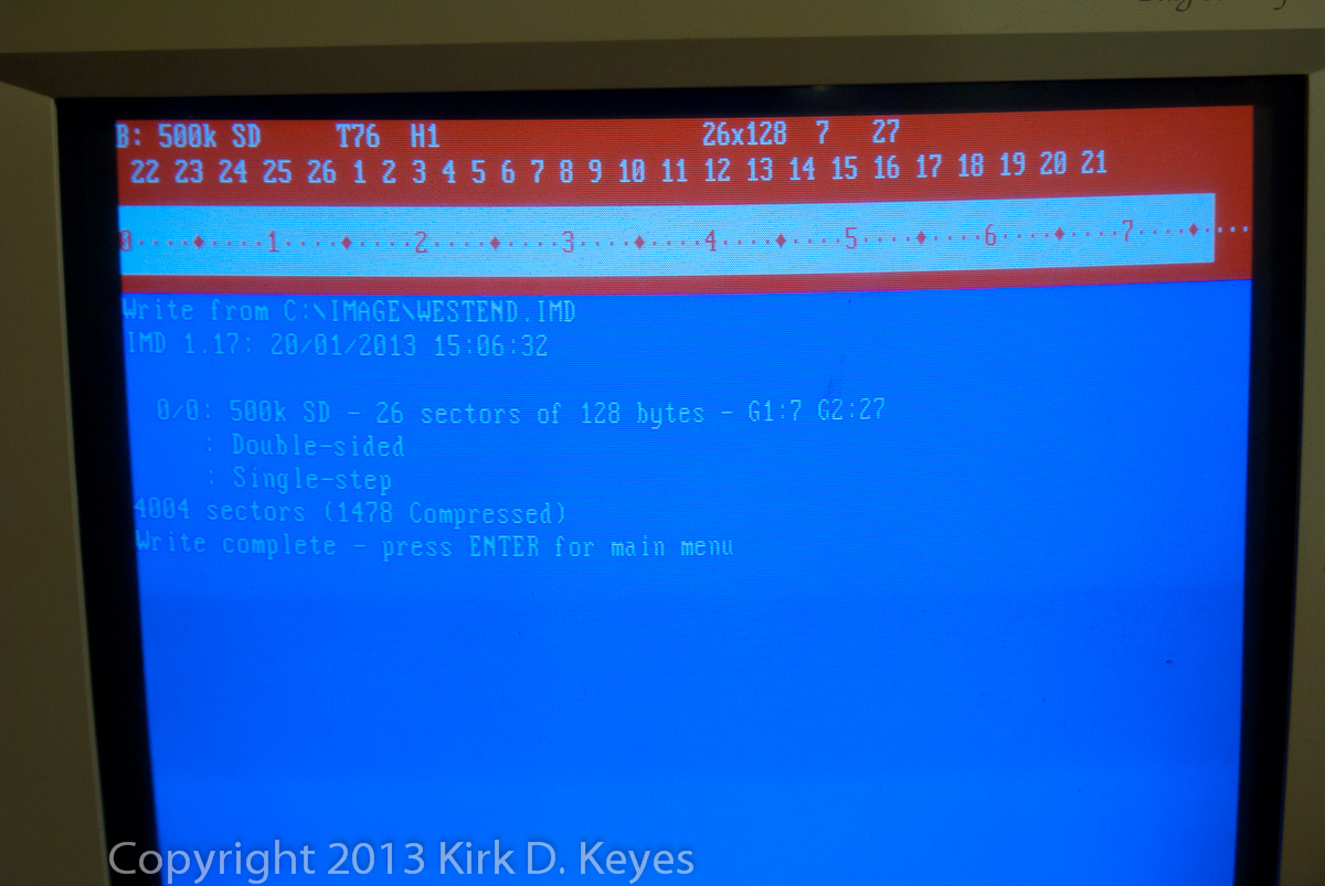
After about a minute, writing is completed!! |
| Proof that the disk imaging worked – putting the disk into the Fairlight and then loading in the files. | |
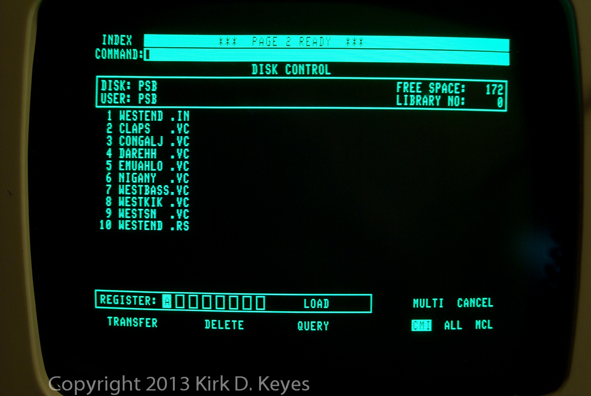 |
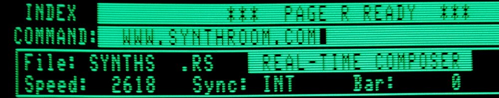
Here’s the Page 2 display for the image that was just written. |
 |
Page 3 after loading the WESTEND.IN file. |
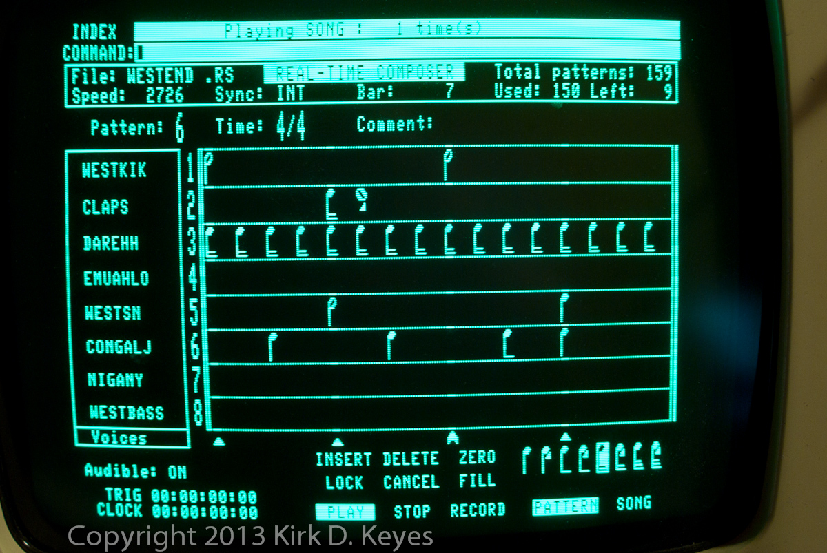 |
Playing the WESTEND.RS sequence file. Here’s Pattern 6. |
 |
And here’s Pattern 10. |
I hope you enjoyed reading about this process. I certainly had a lot of fun getting it all to work!!